Turn Signal Counter
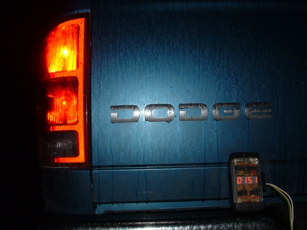
In 2007, I built a circuit which plugged into the trailer electrical connector of my truck and counted the number of times the turn signal blinked.
Technical Details
I used to own a pickup truck, which had a flat 4-pin electrical connector for trailers.
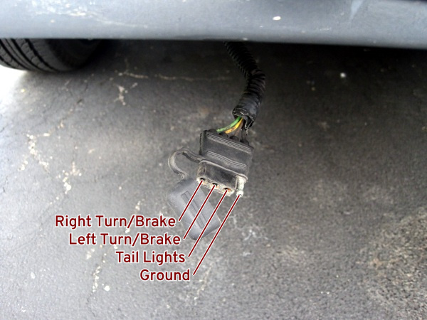
The tail lights pin has a +12 V signal whenever the headlights are on. Since I normally drove with my headlights on anyway, I was able to use this pin for my +12 V power line.
The brake/left pin has a +12 V signal whenever the left turn signal is on the lit half of its cycle or when the brake pedal is depressed, and is at 0 V otherwise. The brake/right pin behaves similarly. I used the brake/left signal to increment the counter. I used rising edge, since these lamps are normally off, so having the counter increment whenever they light made the most sense. With this setup, the counters increment on brake presses as well as turn signals, so it is technically a counter of how many times each of the left and right tail lights have been lit to full brightness. (To avoid this brake capture, I would have had to incorporate logic to increment on the rising edge of the left signal only if the right signal is not also rising.)
Design
I designed the setup for each counter circuit as follows:
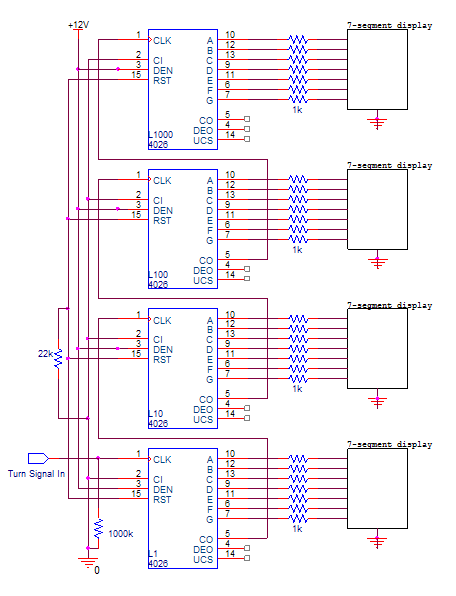
The CD4026BE is a decade counter with 7-segment outputs. It counts from zero to nine and then resets. Carry out is high from decimal 0 to 4, and high from decimal 5 to 9—one cycle per ten clock inputs. Thus, the carry out of one chip can be tied to the clock of the next higher decimal place’s chip to display a proper decimal count.
This is not the most optimal display layout; however, I had an abundance of 1 kΩ resistors, and power consumption was not a concern in this application. It may have been possible to use four counters, a multiplexer, and a single BCD to 7-segment converter rather than four individual ones. However, the only clock signal I had to drive the multiplexer with was the turn signal itself, which only runs at about 1 Hz. Since the turn signal is my data input anyway, it would not have been ideal for me to use it as a clock regardless of its frequency, so I would have been forced to have a separate clock circuit to drive the multiplexer. In the end, I decided that such a setup wouldn’t really be any simpler or more effective than simply using four BCD to 7-segment converters on each counter.
The 1 MΩ resistor was added to control bouncing on the signal input—while not a true debouncing circuit, it worked well enough for a prototype. The 22 kΩ resistor between the RST pins and ground was necessary to get the circuit to reset properly when powered on.
Construction
I initially tested the design on a breadboard.
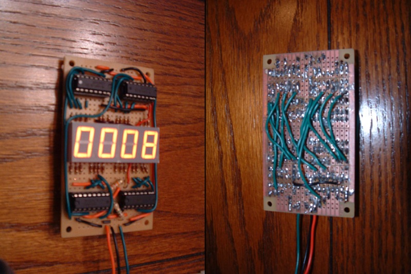
Satisfied that it worked, I soldered it onto a stripboard.
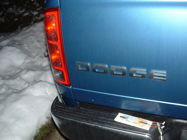
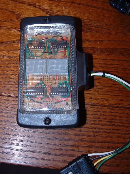
Finally, to weatherproof it, I mounted it inside the case for a spare accessory truck lamp I owned.
I no longer own this truck, and my current car doesn’t have a trailer electrical connector, so this project is complete for the foreseeable future.